
1-805-484-2992
Quotes - Engineering - SalesThe exchanger is designed for the CIP, not just the product
A sanitary heat exchanger spends a few hours a day on product and, over its life, a few thousand hours on cleaning solution. Clean-in-place runs hot caustic, then acid, then sanitizer through the product side at a velocity higher than the process flow. Sterilize-in-place pushes clean steam through the same side at 250 F and holds it. Every one of those cycles heats the unit, swells and relaxes the gaskets, and works the tube-to-tubesheet joints through a temperature swing. The unit that lasts is the one designed with that in mind.
The design questions are specific: what velocity the CIP needs and what pressure drop that creates, which gasket compound survives both the caustic and the acid, how much thermal expansion the bundle sees between a 40 F product and a 250 F sterilization, and whether the construction can be inspected after cleaning or has to be trusted.
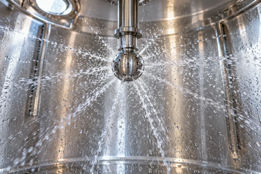
CIP
- Caustic at 160 to 180 F, then acid
- Pressure drop rises fourfold at 5 ft/s
- Rate heads and gaskets for CIP pump head
SIP
- Clean steam at 250 F held 30 minutes
- Expansion 0.1 inch per 10 feet per 100 F
- U-tube bundle or shell expansion joint
Typical CIP and SIP conditions
CIP cycle
- Pre-rinse: Warm water, 100 to 120 F, until return runs clear
- Caustic wash: 1 to 2 percent sodium hydroxide at 160 to 180 F, 20 to 40 minutes
- Acid wash: Nitric or phosphoric, 0.5 to 1.5 percent, 130 to 160 F, 10 to 20 minutes
- Velocity: About 5 ft/s in tubes; 1.5 to 2 times process flow on plates
- Sanitize: Hot water 185 F or chemical sanitizer, then final rinse
SIP and cycling
- SIP: Clean steam at 250 F (about 15 psig) held 30 minutes
- Temperature swing: 40 F product to 250 F steam, several times a week
- Gasket life: EPDM typically 1 to 2 years on daily CIP; less with frequent SIP
- Bundle expansion: Roughly 0.1 inch per 10 feet per 100 F on 316L
- Design pressure: Rated for SIP steam pressure plus any CIP pump head
Design for the hottest, fastest, harshest hour
Building for cleaning and sterilizing
Velocity and pressure drop
CIP works by chemistry and by shear. The chemistry is handled by the skid; the shear is handled by the exchanger geometry and the CIP pump. In sanitary tube a velocity of about 5 ft/s is the common target for turbulent flow that lifts soil from a 32 Ra surface, and on a unit whose process flow gives only 2 ft/s the CIP flow has to be more than double the process flow. That raises the tube-side pressure drop by a factor of four or more, and the tube-side design pressure and the head gaskets have to be rated for it. On plate exchangers the equivalent rule is 1.5 to 2 times process flow, and the port velocity, not the channel velocity, is what limits it.
- Give both process and CIP flow rates on the specification
- Multi-pass tube arrangements raise velocity at the cost of pressure drop; three or four passes are common on small units
- Product on the shell side is hard to clean at velocity; keep it in the tubes
Caustic, acid and the metal
One to two percent caustic at 180 F does nothing to 304L or 316L; it is the reason the exchanger is stainless. The acid step is where care is needed. Nitric acid is passivating and is the safer choice for the metal. Phosphoric acid is common and acceptable. Chlorinated sanitizers and any acid step with chlorides in the water are where 304L begins to pit, and a plant that uses them should be on 316L for the product side.
SIP and thermal cycling
Sterilize-in-place at 250 F for 30 minutes is a modest condition for the metal and a hard one for the assembly. Between a cold product run and a steam hold the bundle grows about 0.1 inch per 10 feet per 100 F, and on a fixed-tubesheet straight-tube unit the shell and tubes fight over that difference at every cycle. Three answers exist: a U-tube bundle that expands freely, an expansion joint in the shell, or a shell-and-tube design short enough that the stress stays within the ASME allowable. The fabricator's thermal design should show which one was used and the number of cycles it was checked against.
Gaskets see the same cycle. Each SIP compresses and heat-ages the elastomer; EPDM that lasts two years on CIP alone may need replacing yearly with weekly SIP, and silicone or a steam-grade EPDM is chosen for joints that are steamed often.
Cleanability by construction type
A gasketed plate exchanger is the easiest to verify clean: open the frame, look at every plate, swab if the program calls for it. It is also the one with the most gaskets and the tightest channels, so particulates and burn-on can bridge a channel and the CIP flow goes around it. A shell-and-tube unit with product in polished tubes cleans reliably at velocity and can be borescoped through the heads, but cannot be opened for a full visual without pulling the bundle. A tube-in-tube unit has one product channel with no bypass path and is the best choice for viscous or fouling product, at the cost of surface per dollar.
Writing CIP and SIP into the specification
Give the CIP chemistry and temperatures, the CIP flow rate, the SIP temperature and frequency, and the sanitizer. Those five items fix the material, the gaskets, the design pressure, the pass arrangement and the expansion provision. Call and talk it through with an engineer: 1-805-484-2992 The case for automating the cleaning cycle in the first place is set out on our advantages of clean-in-place page.
Common FAQs
Yes, and it often is, with the utility side heating the CIP solution as it passes. Make sure the utility temperature does not overheat the caustic beyond its rated range and that the control loop is switched to the CIP setpoint.
Not in the sanitary sense. It fouls like any industrial exchanger and is descaled on a maintenance schedule, usually with the same acid the CIP uses, circulated separately.
Temperature and conductivity on the CIP return prove the solution passed through at strength. ATP swabs at demountable joints and a borescope in the heads prove the result. Plate units add a visual check of opened plates.
A nitric acid step in the CIP maintains the passive layer. If the program uses only phosphoric acid or if the unit was mechanically cleaned, a periodic passivation restores it.
Related
Design & Fabrication
Surface Finish & Electropolish
Grit numbers, Ra values, what electropolish removes, and how to specify a finish the shop can prove.
+ Learn More
Design & Fabrication
Double Tubesheet
Two tubesheets, an air gap, and a leak that shows up on the floor instead of in the product.
+ Learn More
Design & Fabrication
Connections & Drainability
Which fitting standard to use, what size, where the drain and vent go, and how the unit has to sit to empty.
+ Learn More