
1-805-484-2992
Quotes - Engineering - SalesLet the bundle move so nothing else has to
In a U-tube exchanger each tube is bent into a U so both ends land in a single tubesheet at the head end. The bend end floats inside the shell with nothing attached to it, so when the tubes run hotter or colder than the shell they simply get longer or shorter. No bellows, no differential stress on the tubesheet, no limit on how fast the unit can be brought from a CIP rinse to a steam start.
That behavior makes U-tube the default sanitary construction wherever steam is the utility, wherever the duty cycles between hot and cold several times a shift, and wherever a plant wants to pull the bundle out of the shell for inspection or replacement. Sanitary U-tube units are also the geometry underneath most clean steam generators, which are U-tube reboilers fed with plant steam on the tube side.
The trade-off is the bend. The inside of a U cannot be brushed or pigged through, so U-tube units are matched with products that CIP cleans reliably and with bend radii large enough that CIP velocity does not drop through the turn.
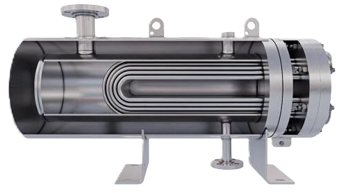
Steam on Monday, glycol on Tuesday, CIP twice a day: a U-tube bundle shrugs at all of it because nothing holds its far end.
Free thermal expansion without a bellows, and a bundle that comes out for inspection.
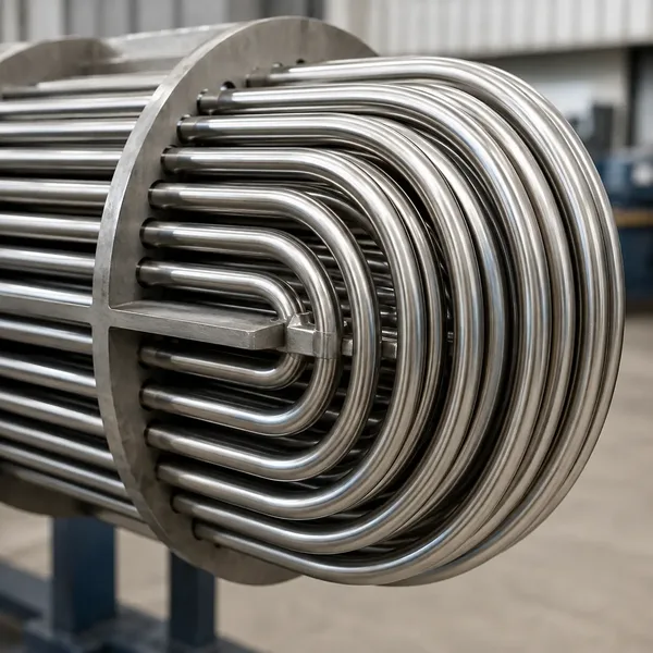
Thermal cycling without a bellows
- Bend end floats free as tubes grow and shrink
- No differential stress loading the tubesheet
- Steam start straight after a CIP rinse
- Fatigue does not build under repeated hot and cold swings
- Shell stays free of any expansion joint
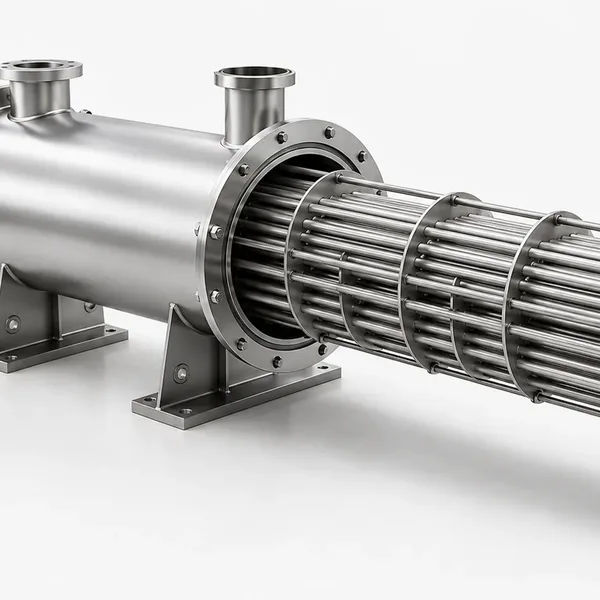
Bundle out for inspection
- Bundle withdraws as one piece once clamps release
- Shell side open for annual inspection
- Spare bundle on the shelf limits production downtime
- Stock bundles held in 304L and 316L
- Replacement bundle built to the original drawing
Built To




U-tube, typical sanitary build
A U-tube unit is quoted to the build below unless your specification says otherwise. Send your pressures, temperatures and connection standard, and every row you change is carried into the quotation.
| Feature | Detail |
| Tube OD and wall | 3/4" or 1" OD, 16 or 18 gauge; 1-1/2" available on large shells |
| Minimum bend radius | Generally 1.5 times tube OD or larger on the innermost row; wall thinning at the bend held under 15 percent |
| Tubesheet | Single fixed tubesheet, product face polished to the tube finish, seal welded |
| Bundle | Removable through the shell flange; replaceable as an assembly |
| Passes | 2 or 4 tube passes (even numbers only); shell single or two-pass with longitudinal baffle |
| Shell diameter and length | 4" to 30" typical; stock patterns from about 4" x 36" to 10" x 54" |
| Design pressure | 150 psig both sides typical; steam to 150 psig on either side |
| Design temperature | 375 F typical; unrestricted thermal cycling |
| Connections | Tri-clamp or ASME BPE product side; tri-clamp, flange or NPT utility side |
| Codes | ASME VIII Div 1 U-stamp, 3-A 12-07, TEMA C; PED, CRN on request |
What to know before specifying a sanitary U-tube
Steam and hot start-ups
Plant steam at 100 to 125 psig sits near 340 to 350 F. Put that on the shell of a fixed-tubesheet unit full of 40 F product and the shell tries to grow while the tubes hold it back; put it on a U-tube and the bundle expands into the free space at the bend end and the shell never notices. The same logic applies to point-of-use coolers that see 180 F rinse water followed by chilled water, and to any unit that will be steamed in place at 250 F or higher between production runs. Where thermal cycling is part of the process rather than an occasional event, U-tube is the construction that does not accumulate fatigue.
Bend radius and cleanability
The bend is where a U-tube earns or loses its sanitary rating. A tight bend thins the outer wall, ovalizes the tube and creates a slow-velocity zone on the inside of the turn where CIP chemistry does the least work. The innermost row is therefore bent at no less than about 1.5 tube diameters and the outer rows proportionally larger; the tubesheet layout starts from that innermost radius rather than from a packing target. After bending, the bend region is inspected for wall thinning and the internal finish is re-verified, because bending can pull the Ra above the spec if the tube was marginal.
With those controls a U-tube cleans as well as a straight tube under CIP. What it cannot do is accept a brush or a pig, and it cannot be borescoped through the return. Products that need those are directed to the straight tube page.
- Innermost bend radius set first, layout follows
- Wall thinning at bends checked and recorded
- Internal finish re-verified after bending
- CIP velocity maintained through the return by pass design
Removable bundles and replacement
Because the bundle attaches only at one tubesheet, it pulls straight out of the shell once the head and shell flange clamps are released. Plants use that for annual inspection of the shell side, for tube replacement as a complete assembly, and for keeping a spare bundle on the shelf so a failure never stops production for longer than a swap. Bundles for common stock shells are held in inventory in 304L and 316L with 32 Ra bores, so a replacement is usually days rather than weeks.
Drainability with a horizontal U-tube
A U-tube bundle mounted horizontally drains its lower legs by gravity and its upper legs only if the bends are pitched to fall toward the tubesheet. The usual approach is to install the unit with the head end slightly low, about 1/8" per foot, and to put the product outlet on the bottom pass. Vertical mounting with the tubesheet down drains every tube naturally and is preferred when floor space allows. Either way, the shell carries a low-point drain and the head carries a drain or is arranged so the outlet is the low point.
A sanitary U-tube is the right unit whenever steam, cycling or bundle access outweighs the ability to brush a tube. Call and talk it through with an engineer: 1-805-484-2992
Common FAQs
Steam on one side and cold product on the other produce a large metal temperature difference. A U-tube bundle absorbs that difference by expanding freely at the bend end, so the shell needs no bellows and the tubesheet sees no differential load. Fixed tubesheet units in the same duty either need a bellows or accept the stress.
Yes, provided the bend radius is generous and the pass design keeps velocity through the return. What a U-tube cannot do is be brushed or pigged, so it is matched with products that CIP is proven to clean.
Two or four on the tube side, since each U is a two-pass element. Four-pass units add a pass partition in the head and are used when the flow is small relative to the tube count and velocity would otherwise be too low.
Yes. Release the head and shell clamps and the bundle withdraws as one piece. Stock bundles in common sizes are generally available quickly; custom bundles are built to the original drawing so the swap is bolt-for-bolt.
Vertical with the tubesheet down drains every tube by gravity and is the cleanest arrangement. Horizontal works well when the unit is pitched toward the head and the outlet is on the bottom pass. Either is acceptable under 3-A when the drains are placed correctly.
They are built to 3-A 12-07 for food and dairy and to ASME BPE for pharma when specified, with the additional bend inspection and finish verification that the U geometry calls for.
Related
Sanitary Exchangers
Straight Tube
Fixed tubesheets, every bore open end to end: the construction to choose when you must see inside.
+ Learn More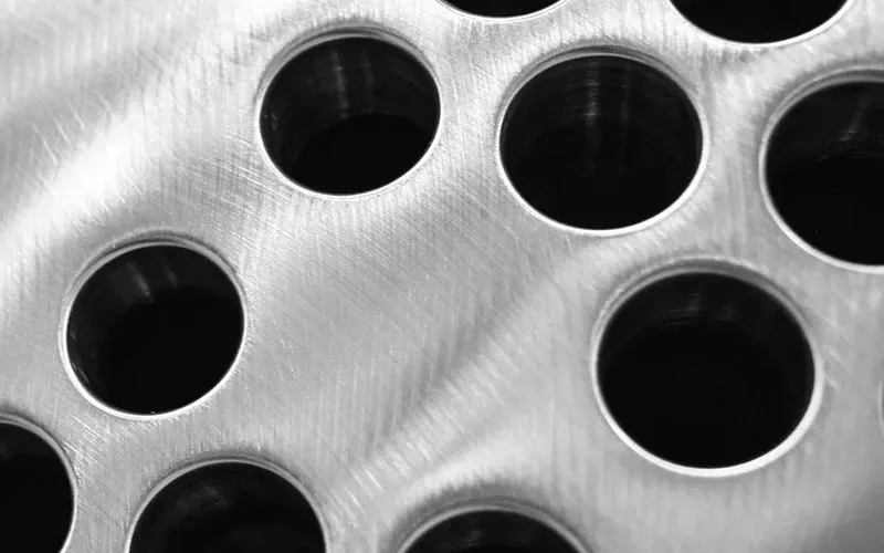
Sanitary Exchangers
Double Tubesheet
Two tubesheets, one open gap, and no path by which utility water can ever reach product.
+ Learn More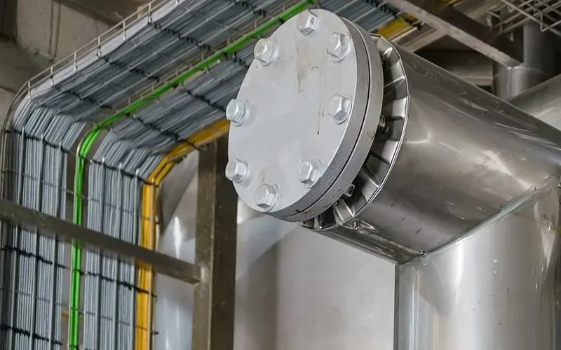
Sanitary Exchangers
Shell & Tube
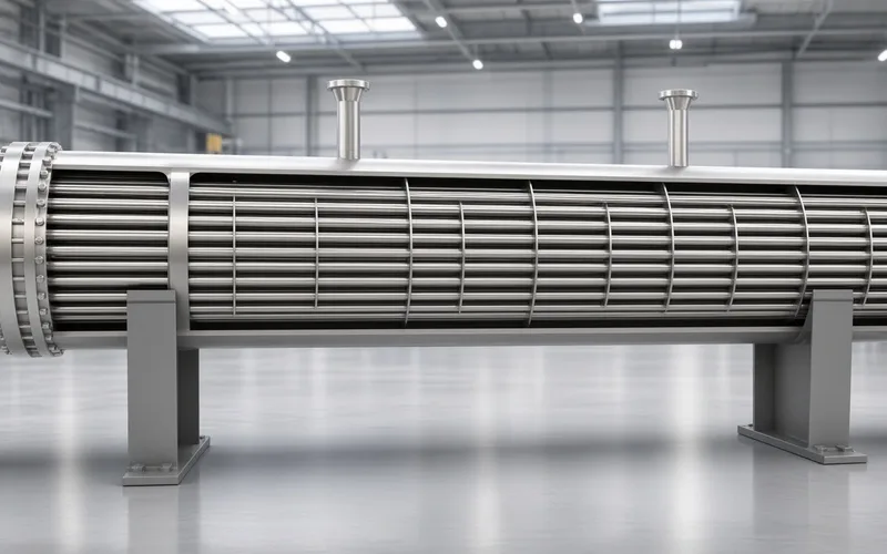
Straight tube, U-tube and double tubesheet bundles built for steam, pressure and a clean CIP return.
+ Learn More